
Copper guide
How to Choose a Patch Panel and Keystone Architecture
The patch panel is the administration point for the copper system. A useful specification connects the panel to the cable, jack or module, rack layout, termination method, labeling plan, grounding approach, and field-test basis.
- Updated
- Reading time
- 7 min read
- Prepared by
- SUNPU technical team
Choose loaded or unloaded architecture
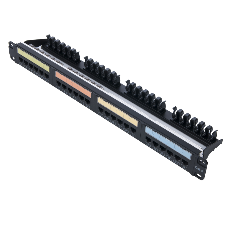
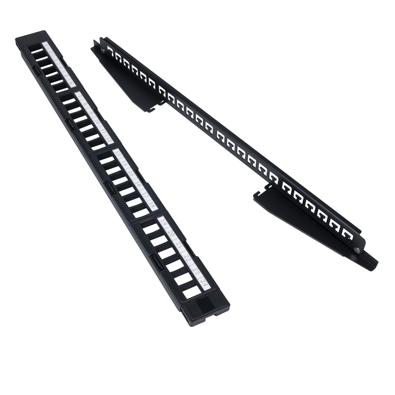
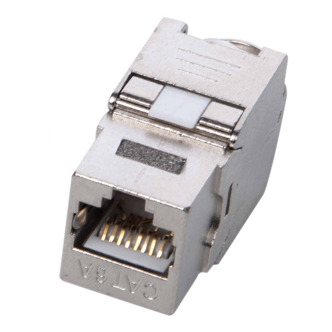
A loaded panel provides a defined port and termination arrangement in one item. An unloaded panel accepts separate keystone modules, which can simplify mixed media, color coding, replacement, and stocking when the opening and latch geometry are compatible.
Record whether ports must be individually replaceable, whether blank positions are allowed, how spare modules will be managed, and whether the same module is used at the work area. Do not assume every keystone fits every panel opening.
- Loaded or unloaded panel
- Module opening and latch fit
- Spare-port and blanking plan
- Work-area module compatibility
Match the termination to the cable
Confirm category, shielding, conductor type, conductor diameter, insulation diameter, overall cable diameter, pair-entry direction, strip length, and any drain-wire or foil handling. These dimensions control fit even when two items share a category label.
Choose punch-down or toolless termination around installer practice, repeatability, available tools, field access, and the approved component set. State T568A or T568B and the expected labeling convention.
- Category and shield construction
- Conductor and insulation range
- Punch-down or toolless method
- Wiring and color-code basis
Plan density and cable management together
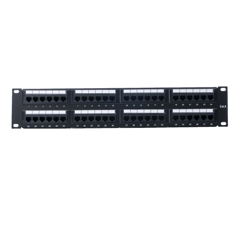
Port count affects rack units, but so do patch-cord diameter, switch position, horizontal managers, rear cable support, bend radius, bundle size, service loops, and access for moves and changes.
Use a rack elevation to show panels, managers, switches, fiber enclosures, power separation, and reserved space. A high port count without a cord route can make a technically valid panel difficult to operate.
- Rack elevation and panel RU
- Horizontal and vertical management
- Rear support and bend radius
- Patch-cord diameter and route
Lock identification and acceptance
Specify panel numbering, port labels, destination labels, label material, replacement labels, and whether the same identifier appears in drawings and test reports.
For screened systems, define bonding and grounding responsibilities across cable, jack, panel, rack, and site. Agree whether acceptance is by component evidence, permanent-link testing, channel testing, or a combination tied to the exact installed configuration.
- Panel and port labeling
- Drawing and test-report identifiers
- Bonding and grounding responsibility
- Permanent-link or channel acceptance
Products used in this decision
Compare the relevant SUNPU configurations.
Apply this guide
Send the current specification, drawing, or product list.
SUNPU can identify missing configuration fields, related components, sample requirements, and product-specific documents before quotation.
Request a technical review →